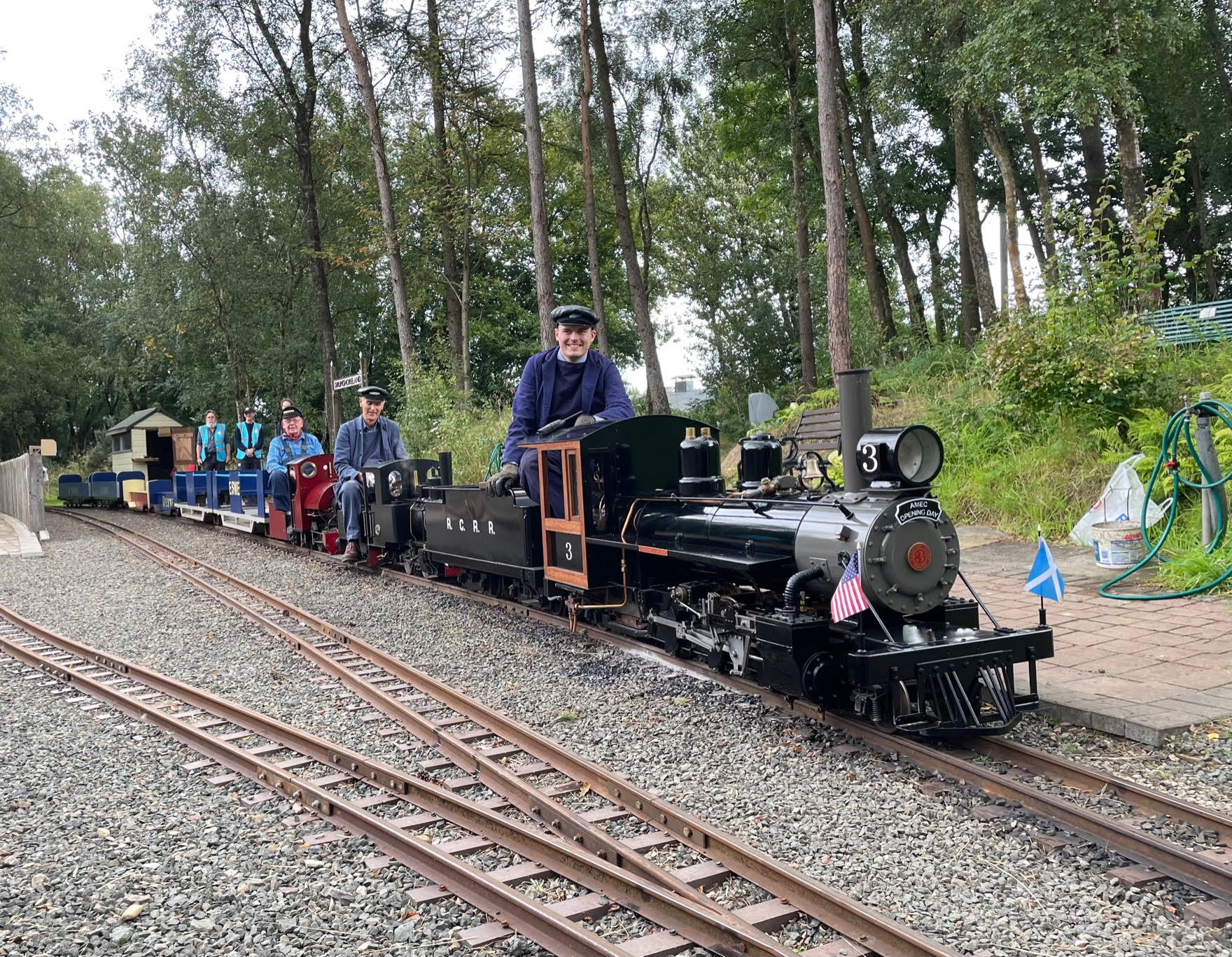
Chris M. has sent in from coldest Edinburgh this update on the Russian Su 251-53. Quite a unique subject to scratch build from a photograph. I am sure we can persuade Chris to tell us the story of how he achieved this in a future article. Meanwhile here is an example of the level of detail Chris is putting into this magnificent machine:
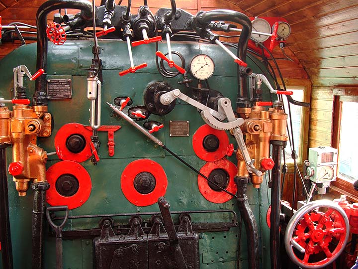
Full size footplate
‘A key feature of the cab arrangement on the Su Class is the shape of the steam turret with its central stop valve and the angled spindle main steam valves. I am not opposed to the purchase of ‘basic’ fittings as long as they are well made and look correct, as the suppliers have spent time and effort to create the production tooling for these to produce them in large numbers. Basic pipe unions and simple globe valves are a prime example.

Shiny paintwork.
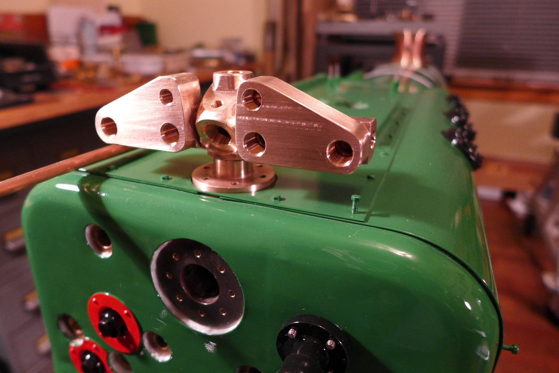
Turret & Cleading
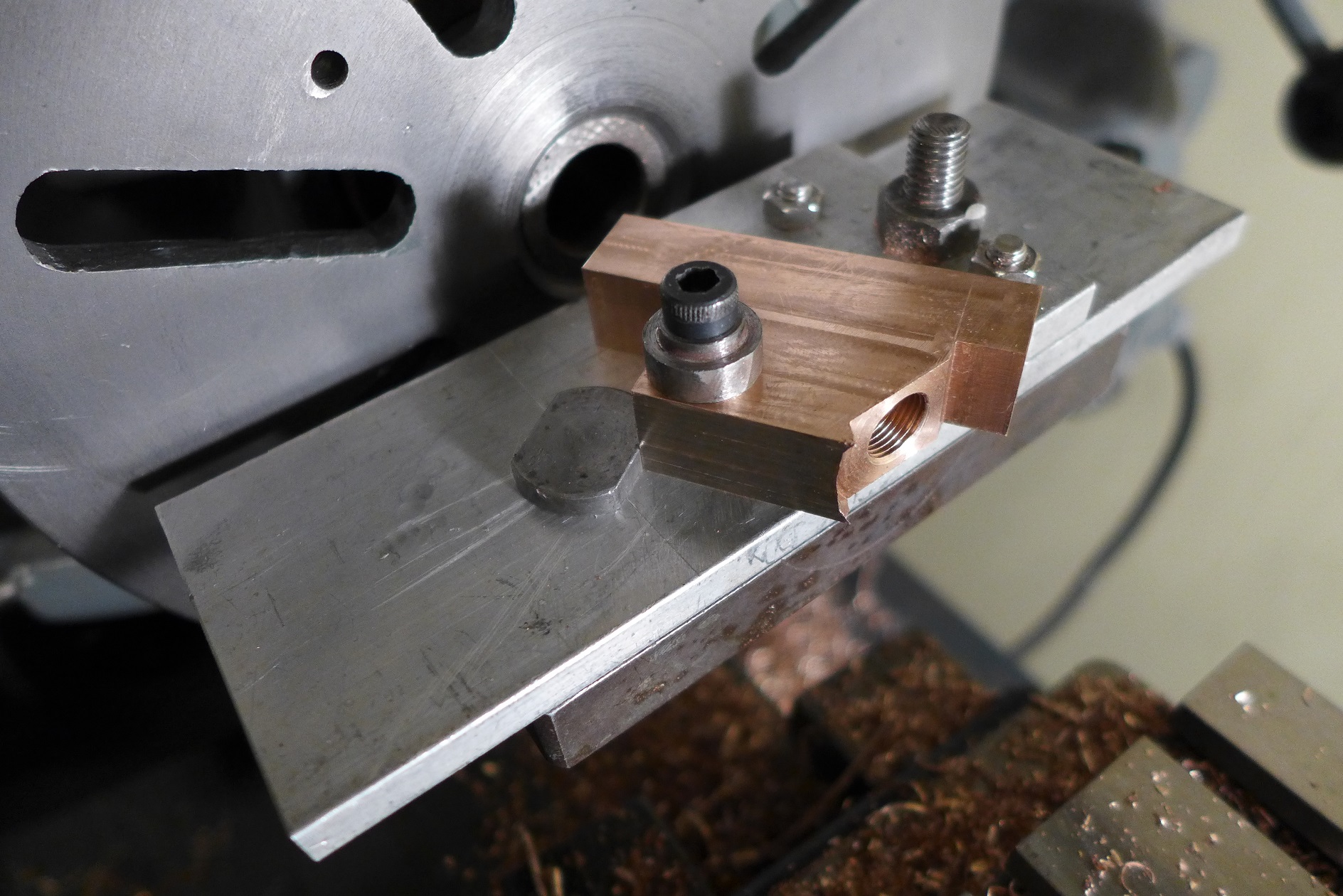
However when the full size practice differs from the basic, there is no alternative than to make the required tooling and make the part from scratch. The turret is machined from a single piece of bronze, so was a ‘bit of a job’ as they say, but turned out successfully. Of note is the large stop valve in the centre, this turned out a swine to get the valve face accurately cut due to the angle and the difficulty in holding the unit effectively to machine the seat. Solved with the manufacture of a valve seat cutter running in the valve body. A LOT of work and a bit galling as in normal service this stop valve is NEVER actually closed. The only time it would be closed is if there was a failure of one of the other valves or as is most likely the whistle valve. Also, whilst the take-off for the pressure gauge is from the turret, it is located above the steam space for the stop valve so always sees boiler pressure, even if the main stop valve is closed.
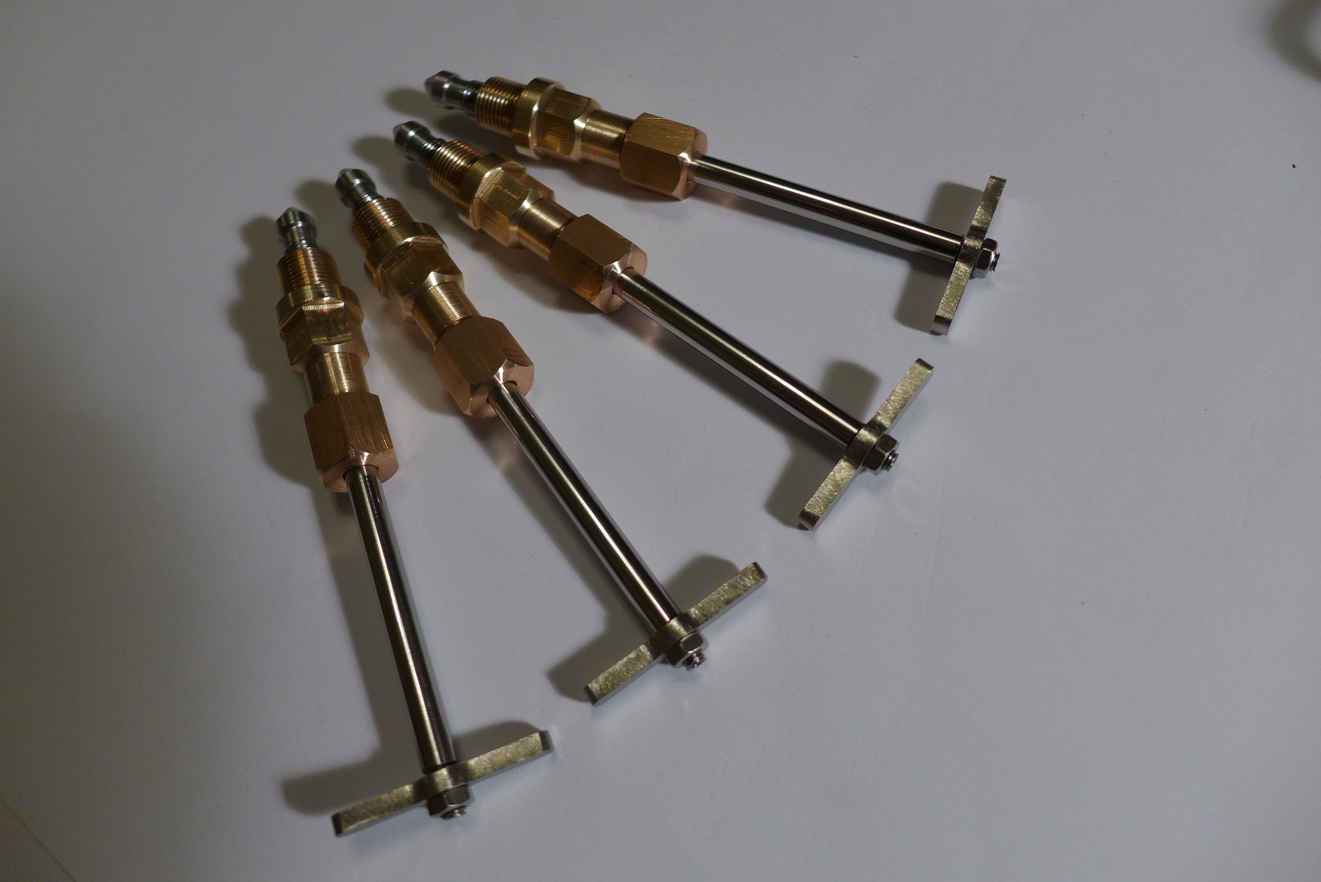
Another example are the four main valves, these are angled spindle valves and dominate the top of the Su’s boiler back head arrangement.
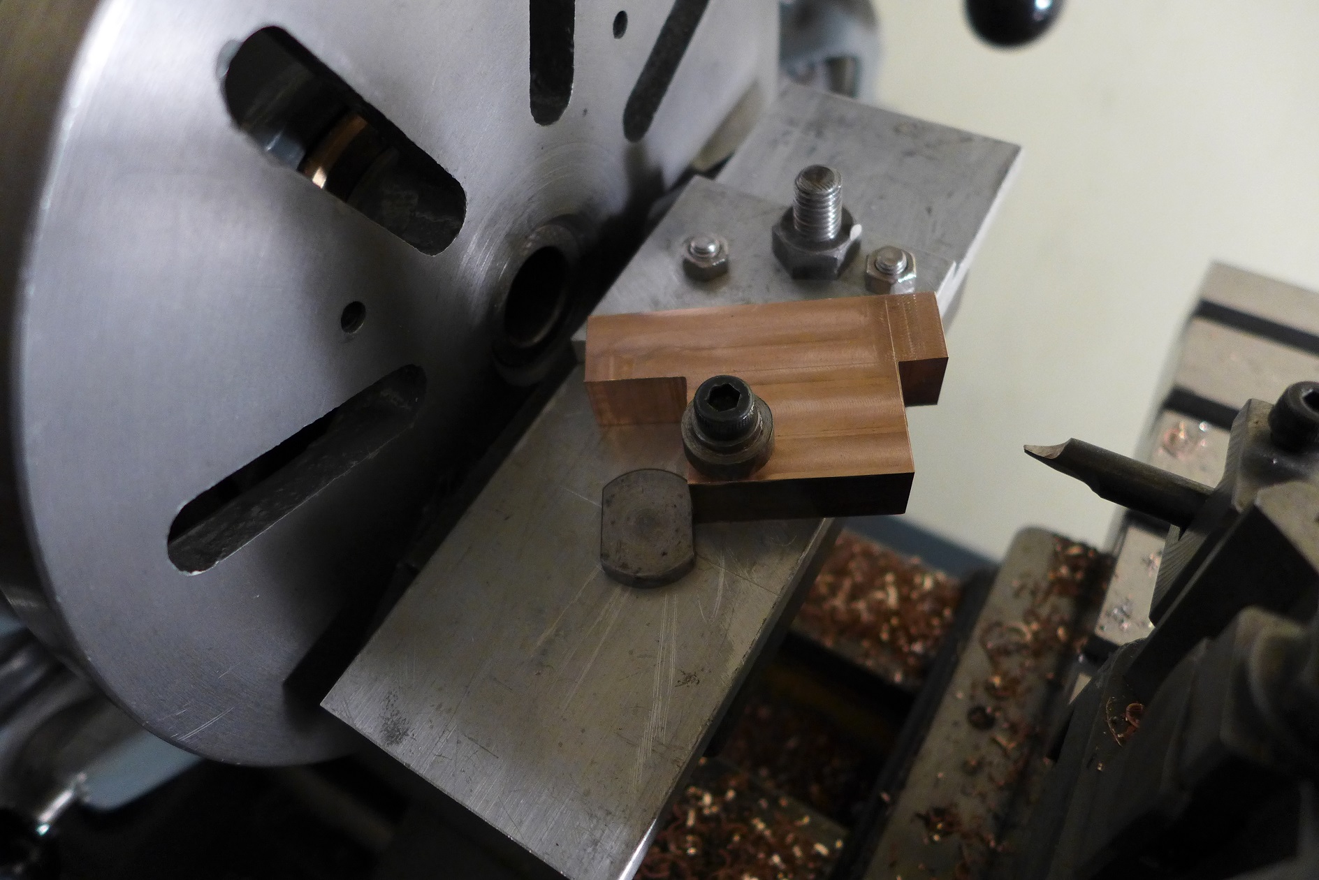
The blank
First thread
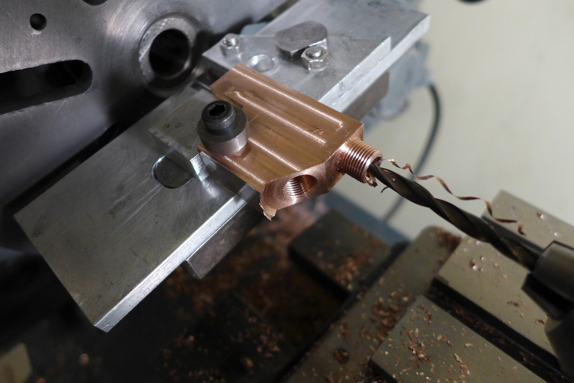
Drilling through
I made all four angled spindle valves the same size, they are slightly over size for precise scale, but I am fairly paranoid on internal cross sectional area so made them large enough to allow good flow.
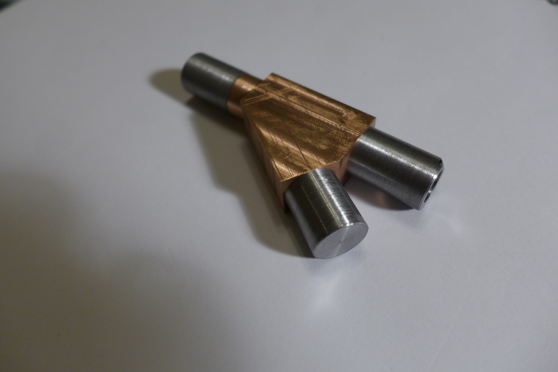
Holding pieces

Milled to shape
I believe the purpose of these valves is that when the spindle is withdrawn in the open position the working fluid (steam in this case) flows in a straight line through the valve so does not have to turn a sharp corner in the valve and lose energy.
Spindles
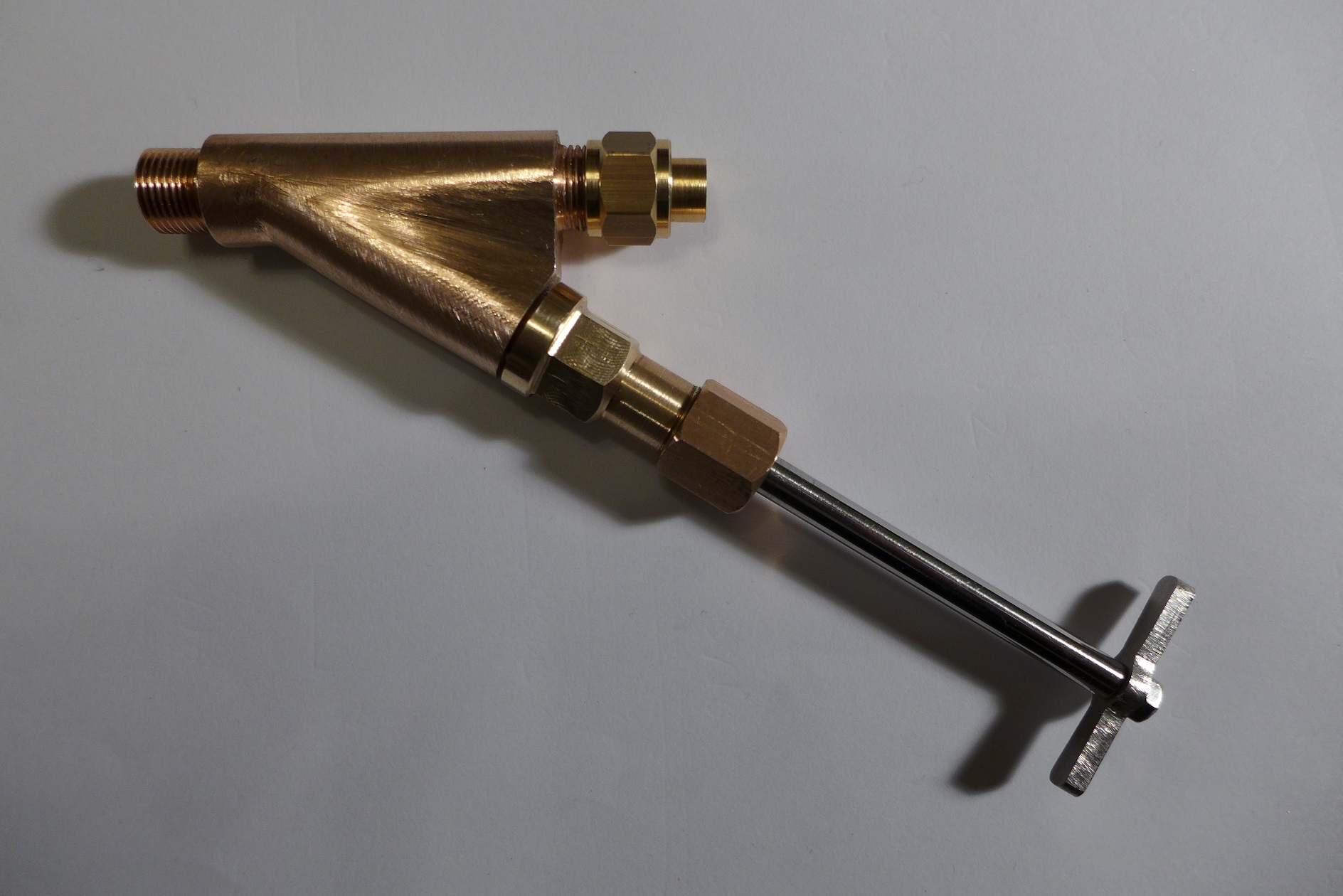
One completed

Turret complete
The pipe from the valve to the injector then has large radius bends to aid flow. In the model valve, whilst not perfect, with the spindle in the withdrawn open position I can see straight through the valve from inlet to outlet, so finger crossed it works OK.
Next tasks are the water gauge, the steam operated cylinder drain cocks valve, and when I pluck up the courage, the two main injectors. They are backhead mounted lifting injectors, so I’m not rating my chances of success and looking at fall back positions on these ones. Even under ideal conditions they are pretty challenging for a number of reasons, lifting from above the tender water level (10” maximum – 5” minimum ) compact size, integral clack valve and the transmitted heat from the boiler. The photo of the full size backhead at the beginning of this update shows these fairly well.
That’s it for now! Stay safe everyone. Best wishes, Chris.’