They really do….!
Member Roger Speirs asks ‘When you’ve stopped groaning, just consider this….
On miniature railway vehicles we need brakes and while steam engines usually have pretty adequate brakes of their own and lots of weight there is something satisfying about piping up to carriages and having a fitted train that will stop dead when you dump the vacuum.
I wasn’t convinced that there wasn’t a simpler way to stop my train so I tried cable operation but while effective I found I needed arms like Arnie to pull up quickly. Then I tried electric brakes which worked really well but took too long to stop me and a loose wire at any time meant no brakes….! Finally after speaking to a very helpful gentleman at the 71/4” AGM at Pickston I took the plunge with vacuum brakes.
Now when I said to him I thought it was a black art and couldn’t see me ever figuring it all out he was very helpful and made it all very clear and simple.
Things like:-
- Leaks might be tolerated on a big system but on a small system you must have a gas tight system.
- No leaks…! Must be a gas tight system. You get the picture….!
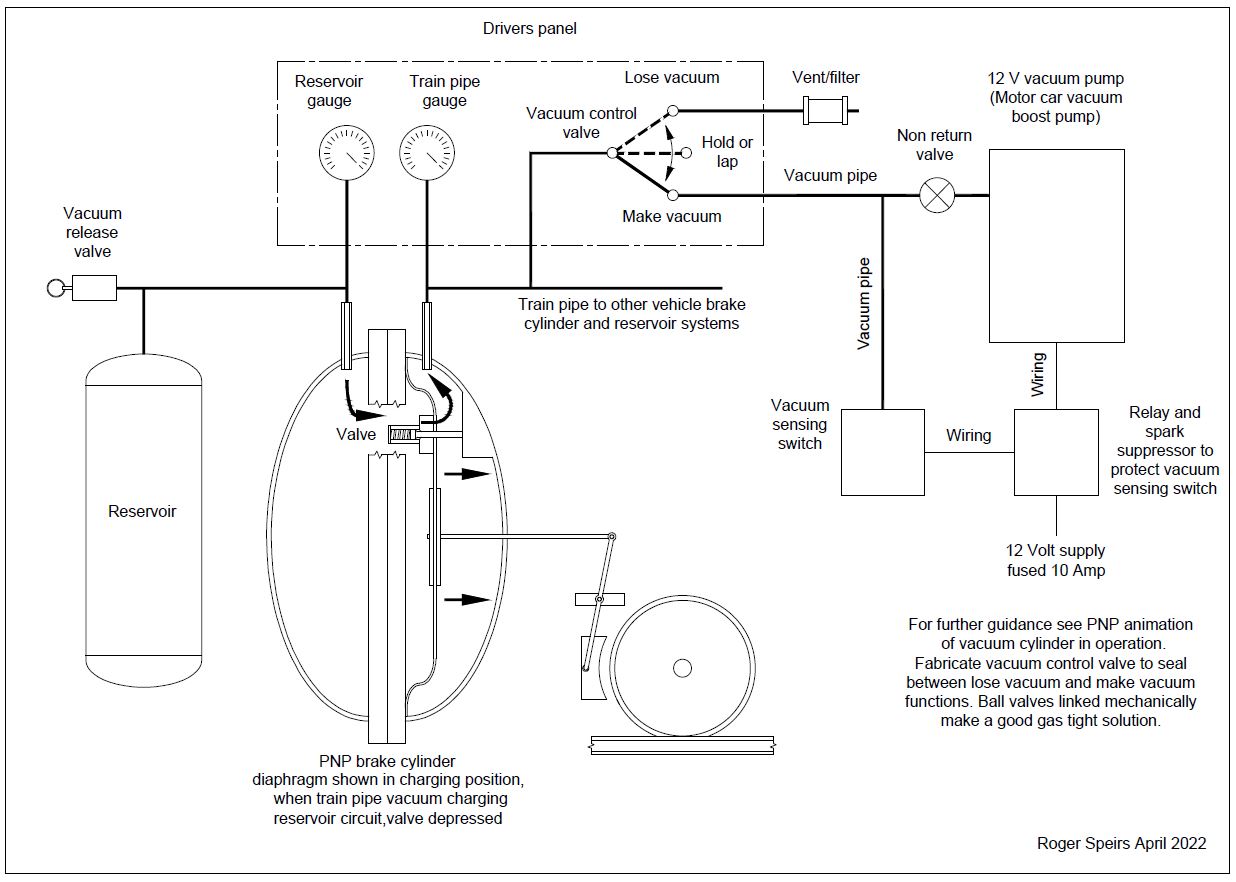
Click to enlarge diagram……
For a system without an ejector you have to have a reliable pump and motor car vacuum boost pumps are ideal. They do vary in price but second hand are very reasonable. I have three now. One Audi and two Mercedes and they all work well. These are all 12 volt electric types and range from £15 to £35 on Ebay. Remember too that you need a 12 volt power source. Electric loco guys have plenty of that….! Others need space for a battery.
Next up is a little one way valve next to the pump in case pump leaks when not operating.
Essential part next is a pressure limit switch. When you reach desired vacuum switch cuts out pump. When you lose vacuum, switch then engages pump again. An electrical man in our club pointed out to me that contacts could burn together so he specced up a relay and spark suppressor to protect the pressure switch.
Now the other end of the system really had me foxed. PNP have info on it but I couldn’t figure out how the reservoir and dump valve were connected to the back of the brake cylinder and no visible means of creating a vacuum there. Even with a kit of brake cylinder bits in front of me I was puzzled. I ‘phoned PNP and after talking to Paul Norman felt a little foolish. His explanation was good and it is so simple. The train pipe side, when vacuum is created pulls on the diaphragm and that pulls over until a little valve is forced open to allow air to be pulled out of the reservoir side until maximum vacuum is created both sides of the diaphragm. Of course the diaphragm returns to the mid position closing the little valve and remains there until you release some vacuum to apply brakes. When you release some vacuum the full vacuum on the reservoir side of the diaphragm acts like a big spring and pulls the brake rod to apply brakes. You simply create more vacuum in the train pipe side to release brakes again.
We’ve dealt with the pump and we’ve dealt with the reservoir and diaphragm but the real problem seemed to be a control valve. Available valves are very pretty and expensive but not gas tight in the main…! If you have charged your newly completed brake system and stepped back and can hear your pump cut in and chirrup every few seconds your system is not gas tight enough. To start with I thought it wasn’t possible to achieve a gas tight system but remembering rules 1 and 2, I persevered…..
Searching did not produce a valve that would do the job so I considered what was available. Ball valves are really efficient and cheap but you need two functions. You have to be able to connect train pipe to pump to create vacuum in system. Then you have to be able to lose vacuum in train pipe to apply brakes. Separately and not at the same time or you would have your pump trying to suck all the air up around you as it would be connected to atmosphere. A simple way round that is to mechanically link two valves together but offset to function the way you want. Train pipe open to pump one way then closed and open to vent other way.
The system on my electric loco driving truck works this way and is pretty much gas tight and efficient. Second generation system on my current project left me with little room to assemble valves and linkage at my control panel. I did try an air valve but it leaked…! So I experimented with a little electric joystick and truck air horn solenoids. Finishing testing by connecting the joystick to assembled components where I‘ve grouped them at the pump again using relays and spark suppressors to protect joystick contacts per our electrical man. It is a really neat solution though joystick needs to be flicked a little to release vacuum in small amounts. Fairly gas tight too. 40 seconds or so between very short chirrups at pump. I might be able to improve on that if I go around the system again checking pipe joints again as in rules 1 and 2….! Even dirt can be a nuisance so remember to fit a filter to the system exhaust. Little chrome and glass fuel filters are available and are a simple solution.
Now who said vacuum sucks…..?’