From the far North Peter B. has contacted us to say that he too has been busy doing a job he had long planned……..
‘With the lockdown causing much time on my hands, I looked at my small metal stock and formulated plans to make more tooling to use with the Myford ML7 or in the workshop.
Having long hankered of an easier way of cutting material such as mild steel, I once again looked into various plans and sketches of small powered hacksaws on the internet.
Having gathered information, I then looked at how I could adapt these ideas to suit my stock and realised that some old bracing bars 30 x 5mm mild steel could form the guide rails, hacksaw frame and parts of a vice.
An old DC motor and controller plus its reduction pulley drive having been salvaged from another person’s old treadmill, would hopefully give me the power base.
Thus, encouraged I sketched up some plans on paper first then drew the main parts in Fusion 360 which would also give me the machine code for use on my home converted Champion 20V mill.
I also purchased a set of plans for the Myford Boy small hacksaw and used the crank mechanism as a basis.
Having laid out the drawings against the available stock.
I also found the old vice leadscrew and nut, that I had kept, thinking that could come in handy one day.
Then started producing swarf.
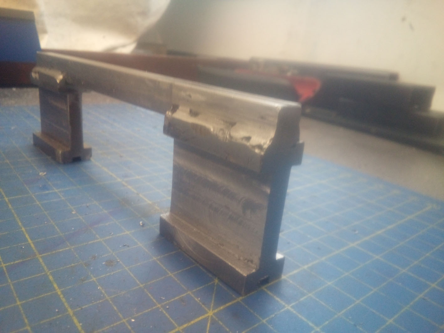 The first item to be made was the slider bar carriage that would have the hacksaw frame welded to it.
This was manufactured out of two surplus pieces of 45mm square steel x 20mm thick, slots roughly milled to a size, welded to a piece of 10mm square bar. Then the slots milled true.
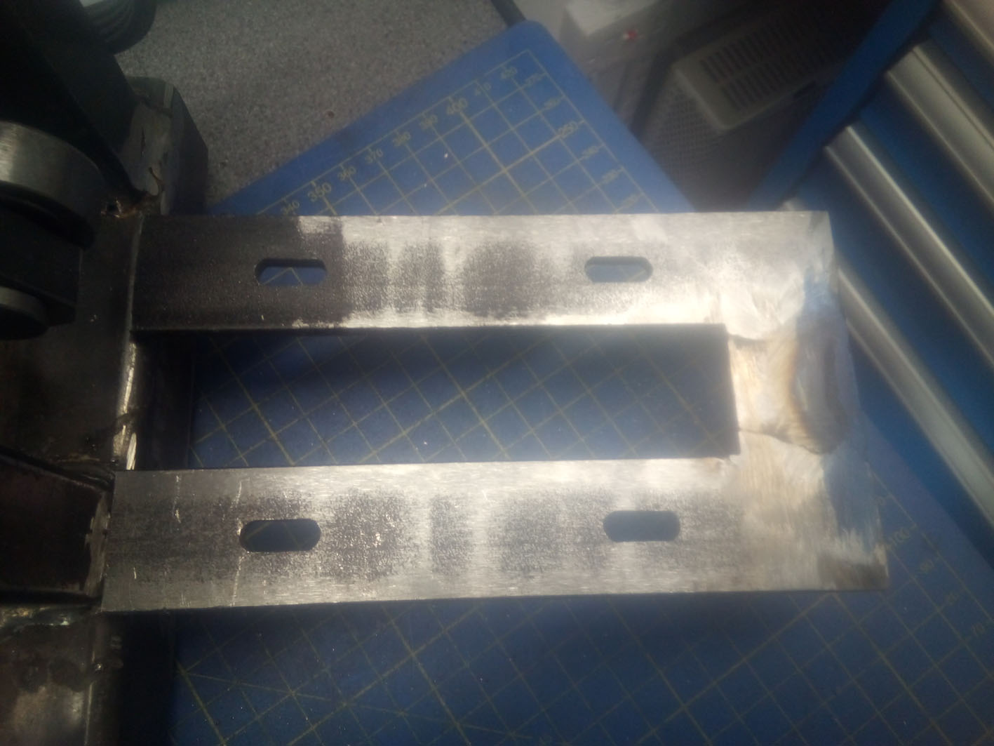
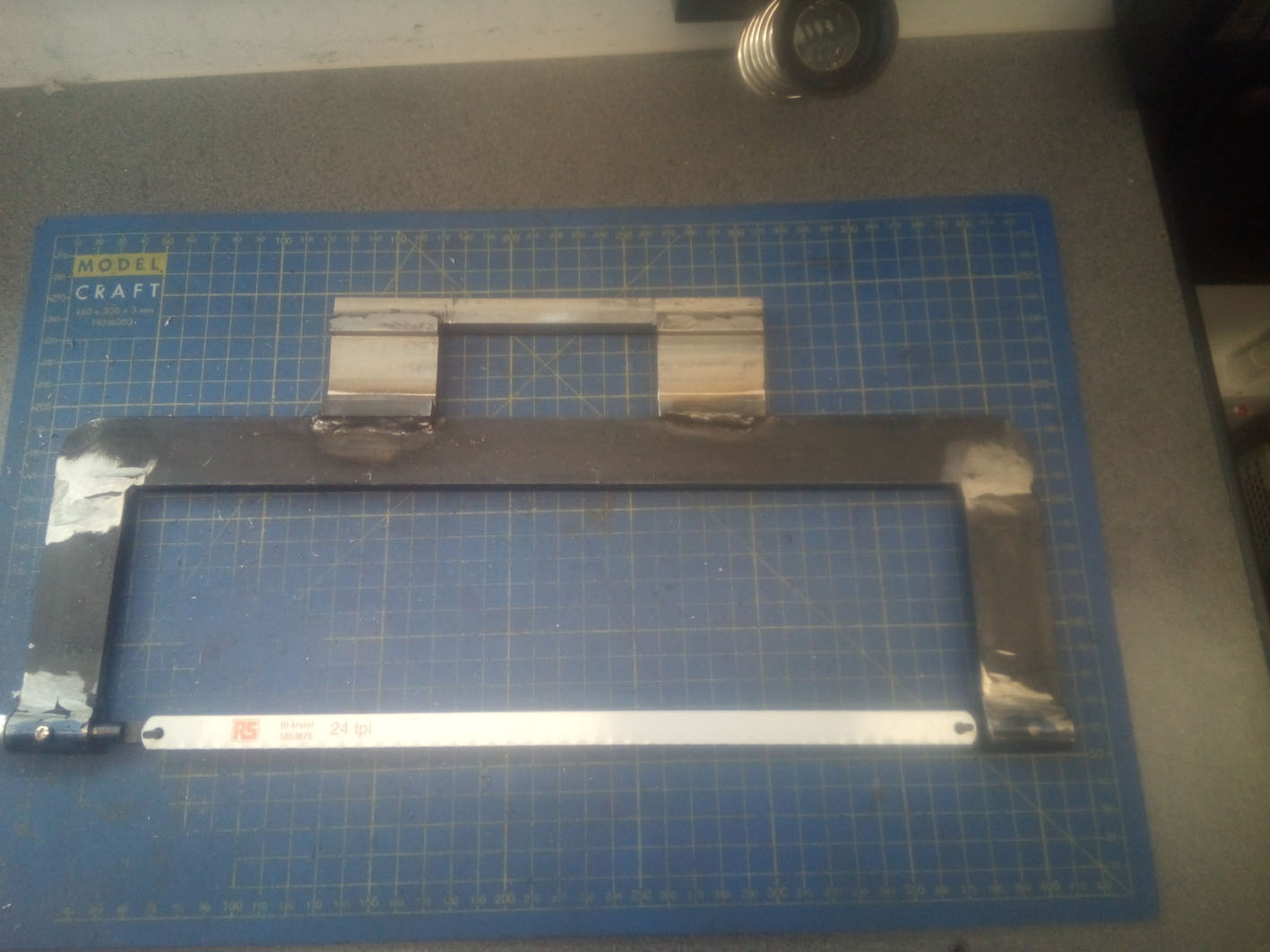 The frame was made up with the 30 x 5mm black bar welded up with two piece of bar which had been bored out to take the hacksaw blade support and tensioner. This was then welded onto the above carriage ensuring it was parallel.
 The guide frame was made from the 30 x 5mm bar cut to length, fitted, and welded to the swing roller support, then its 10mm bearings pressed in.
The next stage was to make the crank mechanisms and for this I drew upon the plans from Myford Boy….
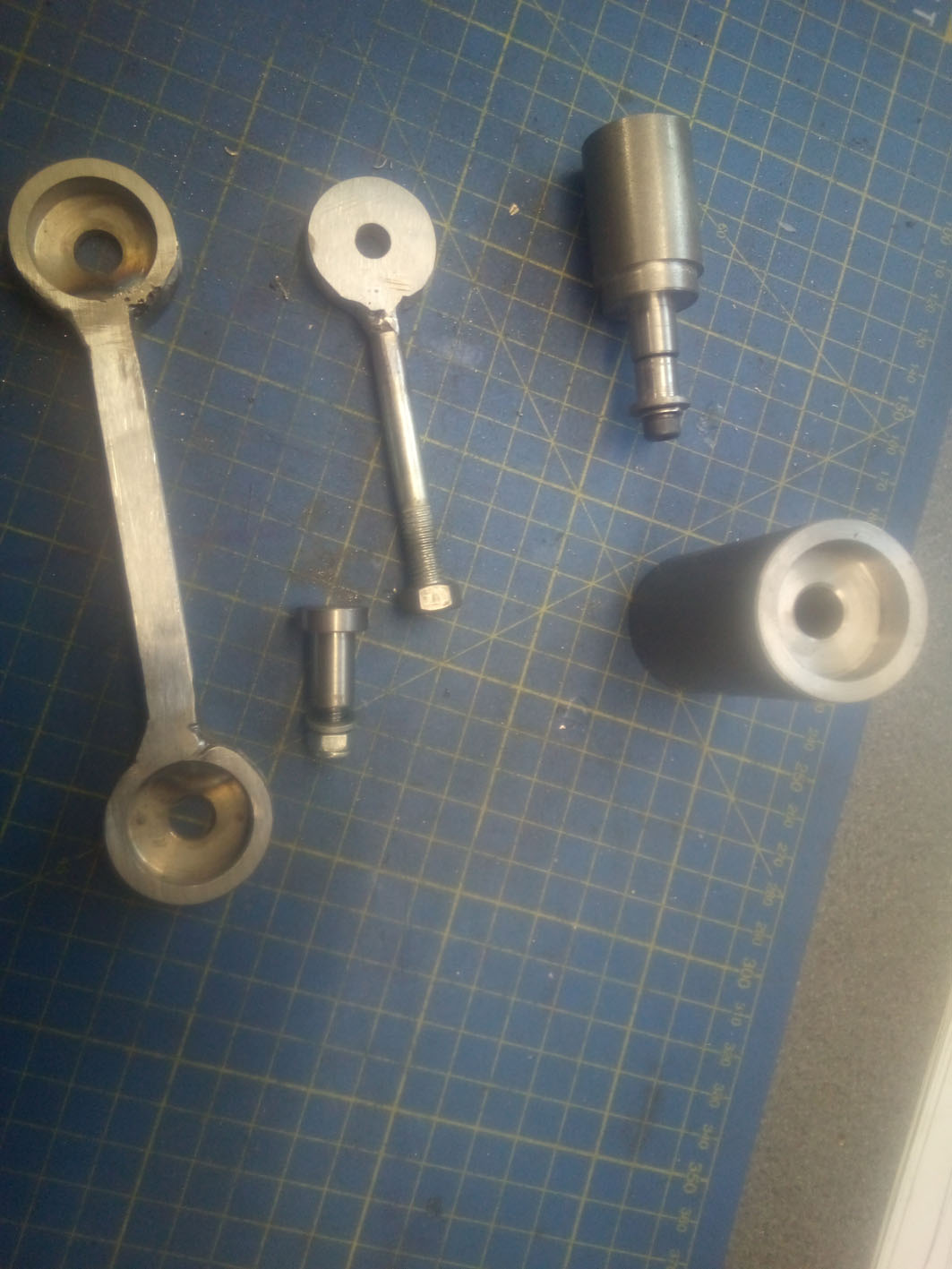 Made a variable stroke crank, its connecting link again from offcuts. The methods used again cutting offcuts by hand. Being rough bored. Welded together.
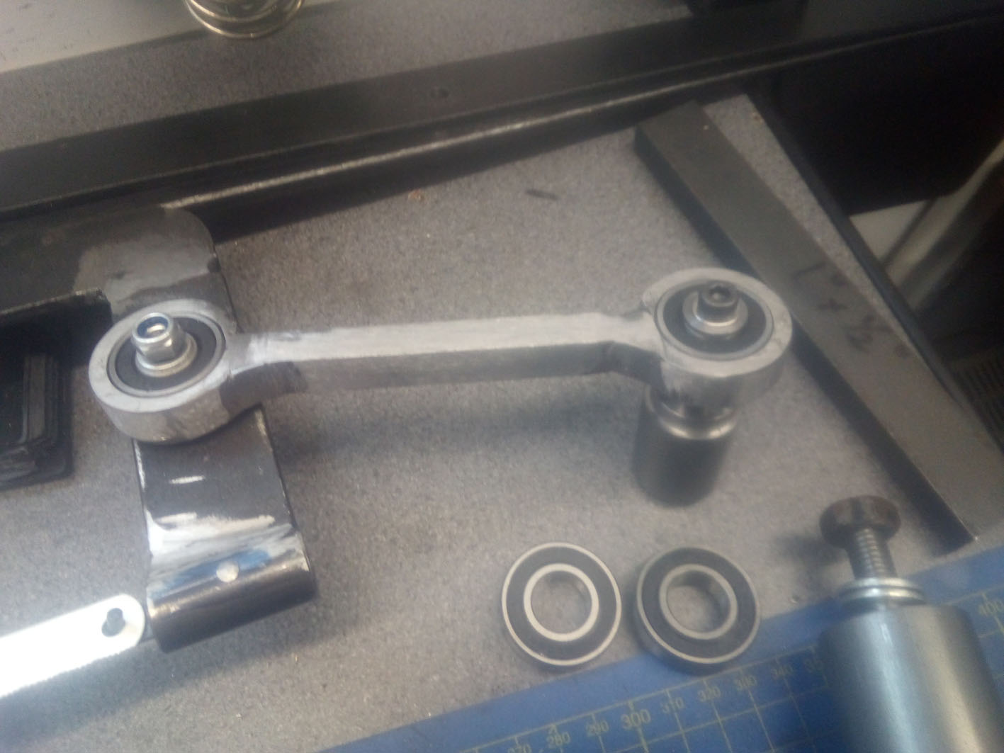 Then trued up and bored to size on the mill. With 10mm roller bearings pressed in. The ball bearings luckily coming via the internet.
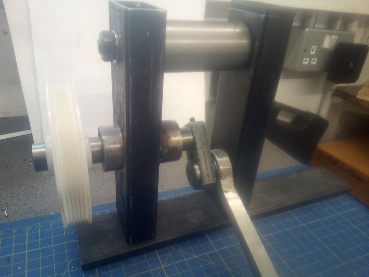 The support frame for the power mechanism was made up from old bits of 50 x 25mm box section offcuts that I had thought of throwing away.
These where bored out to suit the 35mm diameter bearing supports, then welded parallel onto a piece of 40 x 30 box section.
The bearing support was then welded in and 15mm ball bearings pressed in. The whole assembly was then trial assembled to see if it was all true and rotated correctly.
Having successfully got this far, the vice was the next consideration it main base was from made from a piece of 50 x 8mm black bar having a slot milled into it to suit the nut of the old vice leadscrew.
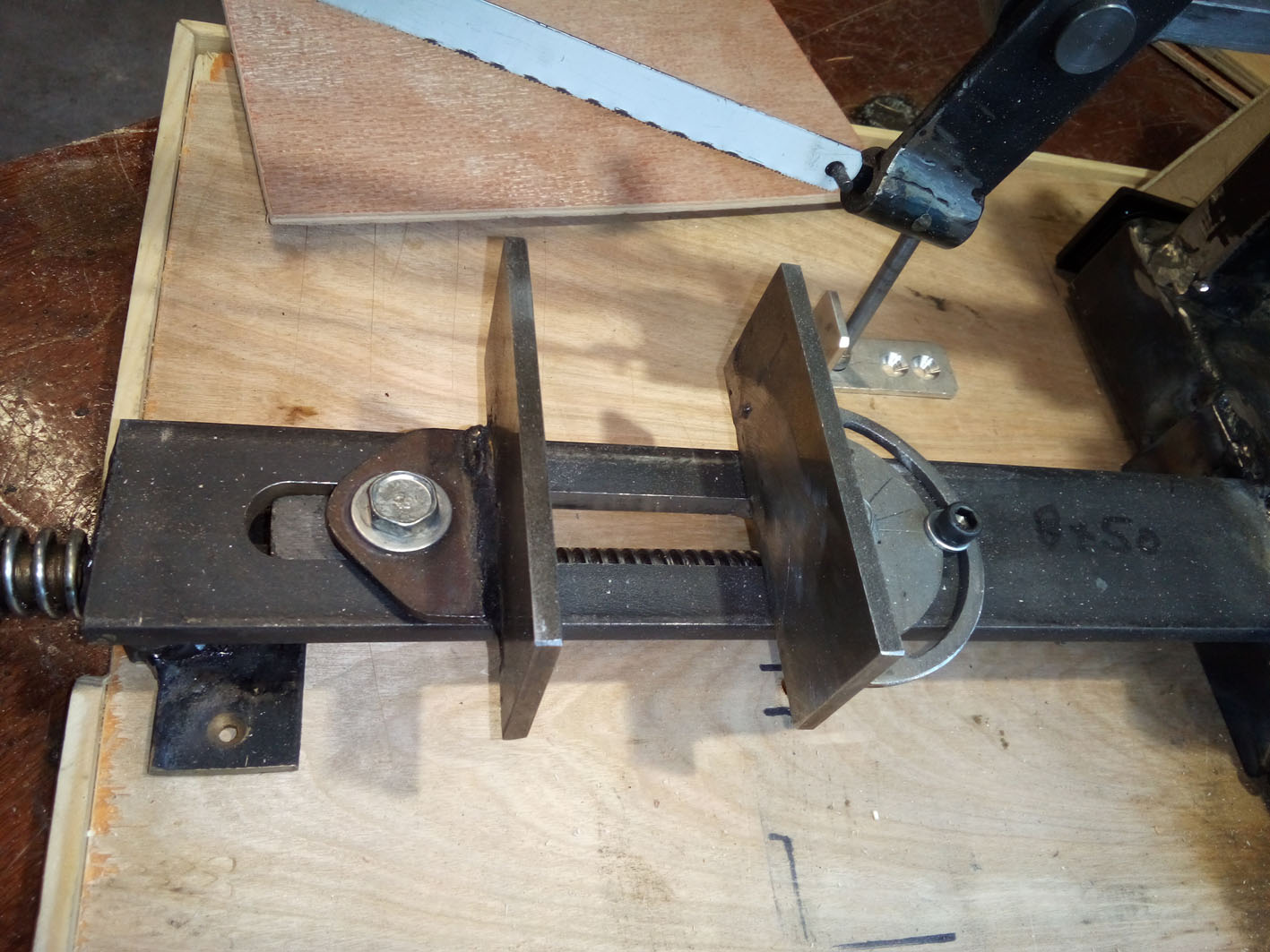 Then supports for the screw where made up and welded into place, the screw and nut fitted and tested.
The Jaws where made up of bits of 3.2mm and 5mm bar offcuts, cut and milled out, then welded up.
The whole assembly then being welded to the support frame parallel to the blade.
 The next stage was to make the motor mounts incorporating a simple screw belt tensioner. Again, the remnants of the 30 x 5mm bar was used.
Cut and Welded up. Slots milled and then welded up to the main supports ensuring the alignment of the pulley would match.
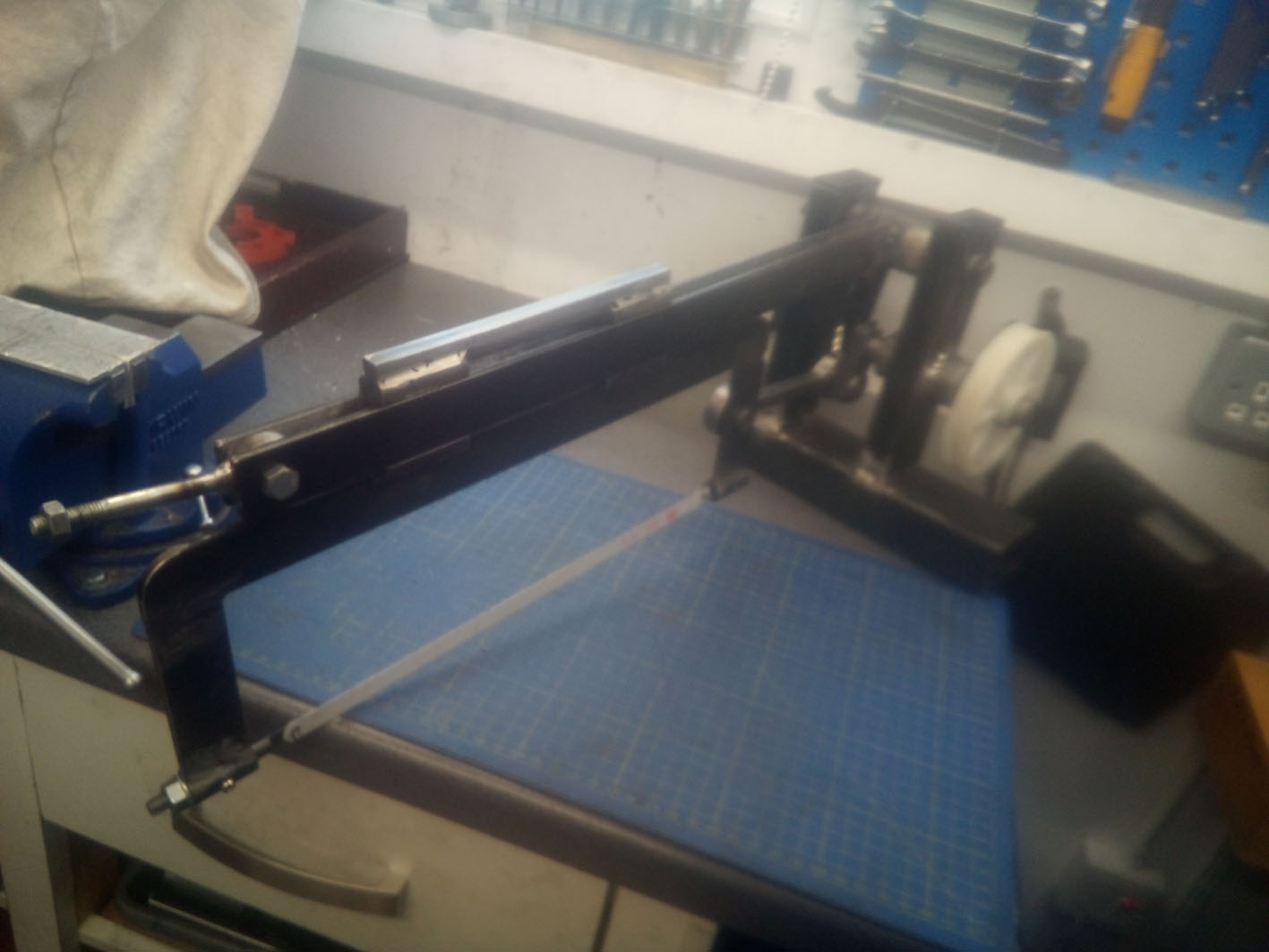
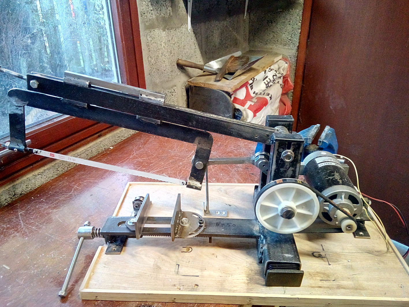 The motor and mechanism were then connected to the speed controller by a jury rig, well earthed and power switched on.
All went well despite the motor starting at full speed and the whole rig trying to skate of the bench despite the clamps, and it cut a piece of 12mm mild steel test bar.
The ongoing stage was to make a base out of a piece of old 18mm ply, edged with beading to give a tray.
A roller blade stop was manufactured utilising a 10mm roller bearing along with a swing support bar for the frame.
The motor housing is currently being made out of plywood and will be fitted with an old computer fan to cool the motor, the controller, fuses and on off switch.
A Suitable motor stop mechanism utilising a limit or other switch is intended.
Then to strip it all down, clean, paint, reassemble and use.’