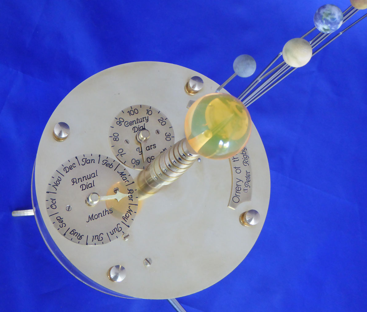
Member Peter R has dropped a line to the Newsdesk from rural Nantwich updating us on his latest fascinating project. Peter wrote in November 2020 describing his Orrery & in April this year described his Heliochronometer. Peter takes up the story:
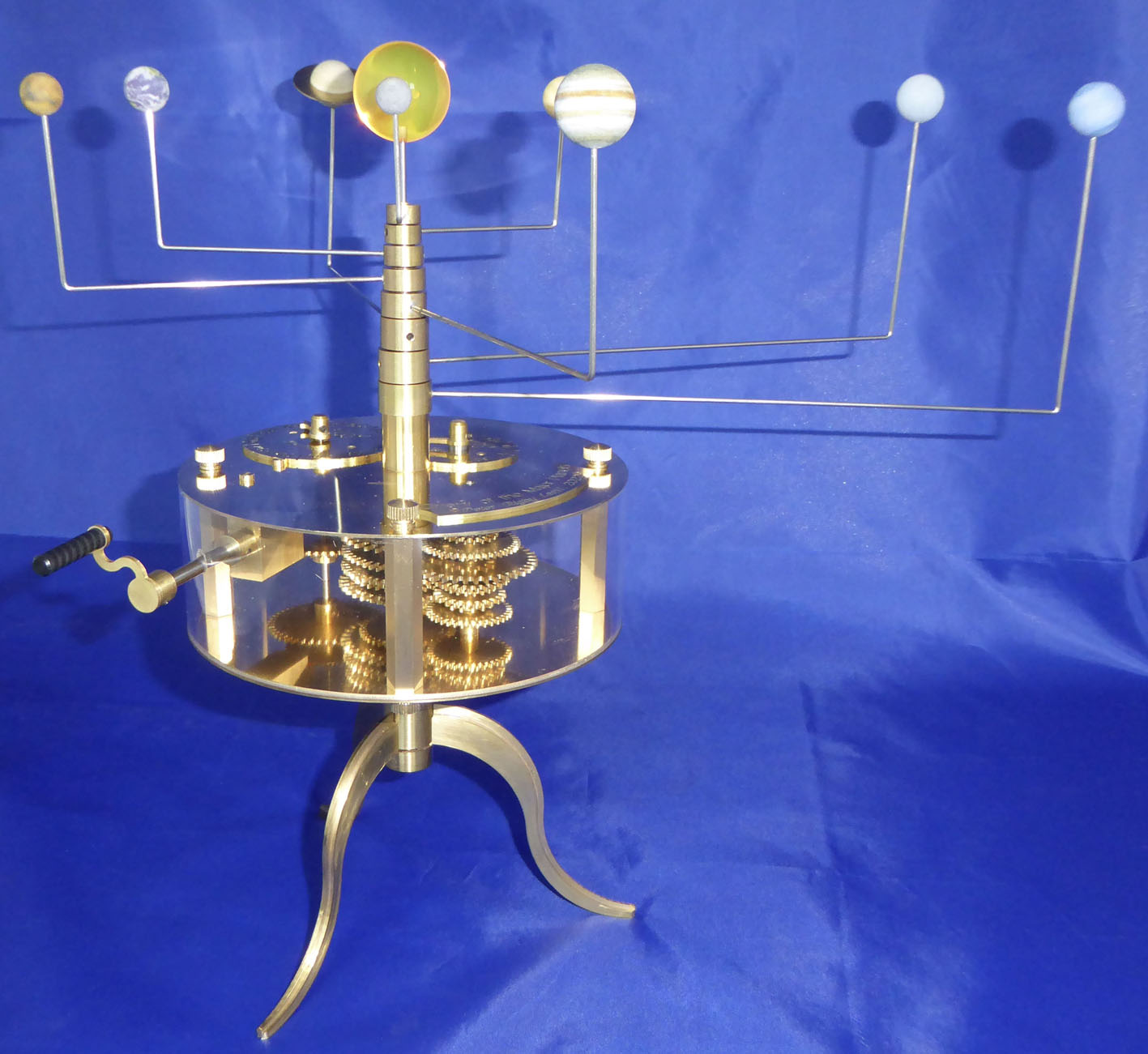
‘Many orreries produced in the 18th and early 19th century were constructed with the gear mechanism hidden in a large diameter, shallow brass drum. Usually mounted on tripod legs with the planet arms arranged above the drum. Why the operating mechanism was hidden away like this I am not sure. There was a practical reason to protect the gearing, but I also suspect it was partly to avoid the distraction of the viewer from the complexity of the motions of the planets and partly to protect the orrery builder’s secrets of how their particular mechanism worked – it was a very competitive world!
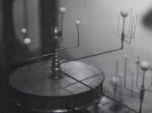 I had thought it would be nice to design such an orrery but still have the mechanism on view and yet protected.
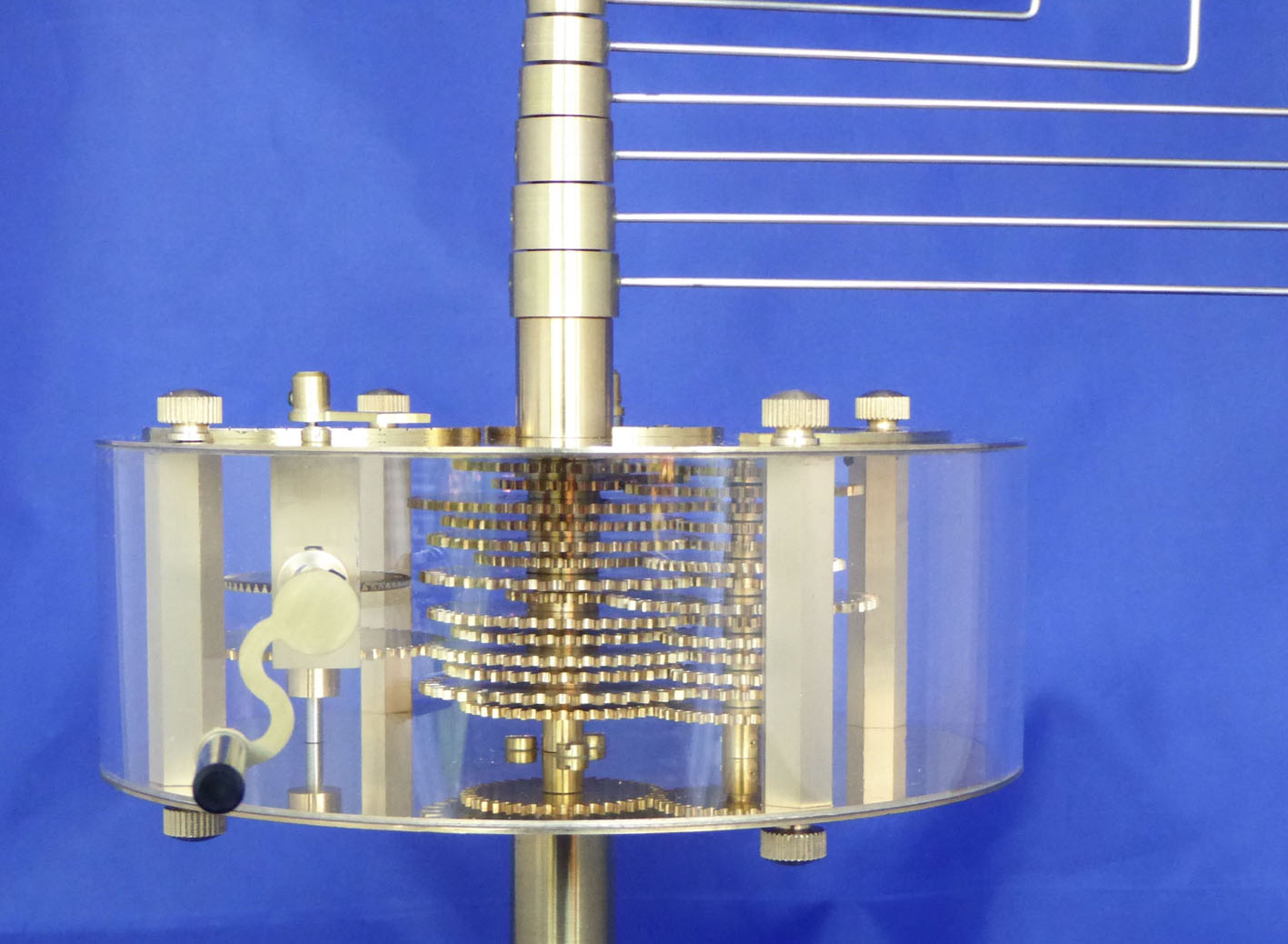
I had a short length of perspex tube about 6 inches in diameter left over from a low temperature Stirling engine I had built a number of years ago, and this seemed perfect for a transparent gear drum. The only problem was that its diameter was rather small for this purpose. Most drum type orreries had a diameter of 12 to 15 inches, so fitting the gearing in and yet achieving the required gear ratios would require careful thought. In this type of orrery the planet arms are driven by a series of concentric shafts, 8 in total for the major planets.
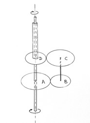 The usual arrangement is a cascade of reverted gears, where the input and output of each stage are on the same axis as shown in the sketch.
If the gears have their teeth on a fixed pitch circle diameter (PCD) this limits the potential ratio achievable, since the total number of teeth on gears A and B must equal the number of teeth on gears C and D. This is not usually a problem in most engineering applications where the design allows a tolerance on the required gear ratio, but it is a problem where a very precise ratio is required as in horology.
The answer is to allow different PCD’s for each pair of gears. The A and B pair must have the matching PCDs, but the C and D pair can have a different PCD in order to meet the requirement of common input and output shafts. This however is a potential nightmare for the gear cutter, since different cutters are required for different PCDs. I had a solution however, and that was to cut all the gears on my small CNC router. There is an app on the web that will produce the drawings for cycloidal gears with any number of teeth on any PCD which you require. My only limitation was the minimum size router bit I can reliably use on my router to cut the teeth. Experience has shown that 1 mm diameter is fine, but at a push I can go to 0.8 mm when cutting brass sheet 1.5 mm thick.
So given the constraints of the small perspex tube and the smallest tooth pitch of 1.6 mm I set about calculating the required gears for the highest accuracy achievable. All 14 pairs of gears had slightly different PCDs. For the set of 8 concentric drive shafts I used Albion Alloys brass tubes. They are available in increments of 1 mm diameter with a wall thickness of 0.48 mm, so they stack very nicely inside each other. All other parts such as the drum ends and the tripod legs I also produced on the CNC router. The shafts are silver steel or stainless and all gear hubs and fixings are turned on the lathe in brass. The gears are a light push fit onto their hubs and secured with Loctite 603.